Step by step
This series builds upon the Introduction to Orchestrator and will get you started using the plug-in. If you have not yet reviewed the Godot Step-by-Step Guide, we strongly recommend doing so before proceeding.
Creating your first orchestration
In this lesson, you will code your first Orchestration to make the Godot icon turn in circles using Orchestrator.
As we mentioned in the introduction, we assume you have read all the prerequisites.

Project setup
Please create a new project to start with a clean slate. Your project should contain one picture: the Godot icon, which we often use for prototyping in the community.
Install the plug-in
Before we can proceed, we need to install the Orchestrator plug-in. The plug-in can be installed from the Godot Asset Library or manually by downloading from our GitHub repository.
See the Installation Guide on how to install the plug-in.
Creating the scene
We need to create a Sprite2D node to display the Godot icon in our game.
In the Scene view, click the Other Node button.
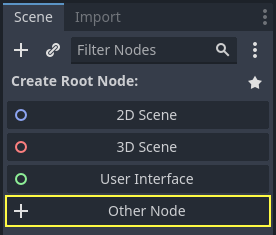
Type "Sprite2D" into the search box to filter the nodes, double-clicking on Sprite2D to create the node.
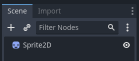
Once the Sprite2D node is added, your Scene view should now look like this:
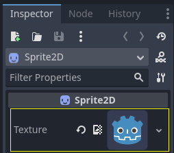
A Sprite2D node requires a texture to display.
In the Inspector view on the right, the Texture property shows that it is empty.
To display the Godot icon, drag the file icon.svg from the FileSystem view onto the Texture property in the Inspector view.
You can create Sprite2D nodes automatically by dragging and dropping images onto the viewport.
Lastly, click and drag the icon in the viewport to center it in the game view.
Creating a new orchestration
To create and attach a new Orchestration to our node, right-click on the Sprite2D in the Scene view and select ![]()
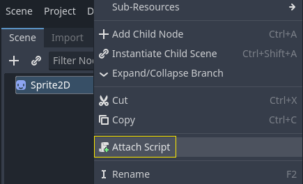
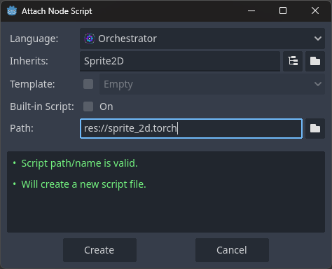
The Attach Node Script dialog will appear.
This dialog allows you to select the script's language, the file path, and other options.
Make sure the language is set to Orchestrator, leaving all the other options as their defaults.
Click the Create button to create the script.
The Orchestrator ![]()
sprite_2d.torch orchestration open.
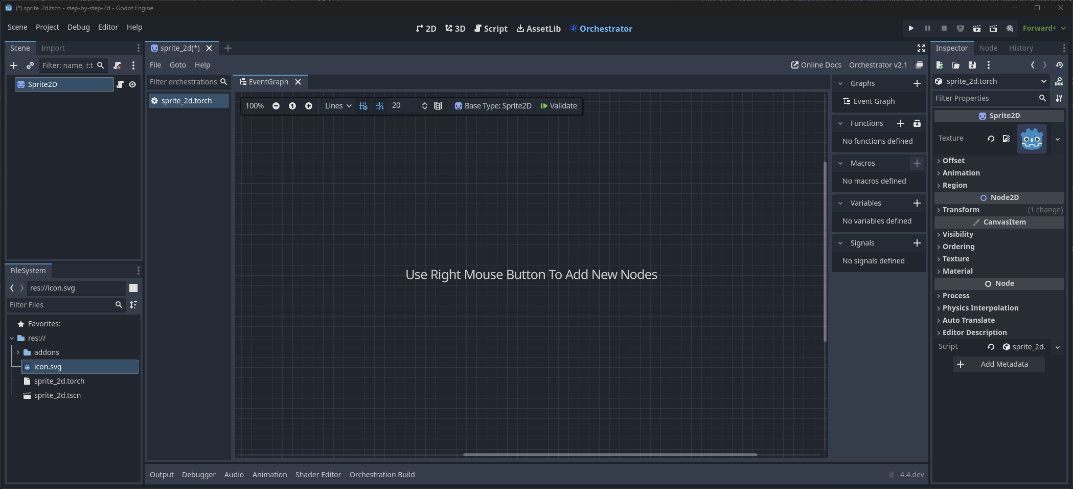
Hello world!
Our Orchestration script currently doesn't do anything.
Let's make it print the text "Hello, world!" to the output bottom panel to get started.
- Right-click the graph to open the All Actions dialog.
- Search for
Print String, and select thePrint Stringaction. - To add the node, either press the Add button or simply hit Enter.
- Change the value of the
Textparameter toHello, world!.
Lastly, we need to add a Godot event callback so that our Print String node outputs the value.
- Press the button located at the top right of the Functions panel.

- Search for the
Initaction, found in the Methods > Objects category. - To add the node, either press the Add button or simply hit Enter.
With the two nodes in the Graph, using your mouse:
- Left-mouse click the white output arrow on the right side of the Call Init node.
- Drag from this output pin to the input arrow on the left side of the Print String node.
If done successfully, the two nodes should be connected.
The Init event is a special callback that represents the _init() function in GDScript, which acts like a constructor.
The Godot Engine calls this _init() on every object or node when it gets created, as long as this function is defined.
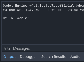
Now, save the scene as script_2d.tscn if you have not already, then press F6 (Cmd+R on MacOS), to run it.
Look at the Output panel in the editor, it should display "Hello, world!".
Lastly, we need to remove this "Hello, world" logic, so:
- Click on the Print String node, and right-click, selecting the Delete option to remove the node.
- Click on the _init entry in the Graphs section of the Component Panel.
- Right-click and select the Remove option from the context-menu.
You should end up with an empty canvas.
Turning around
It's time to make our node move and rotate. To do so, we're going to add two member variables to our Orchestration:
- The movement speed in pixels per second
- The angular speed in radians per second
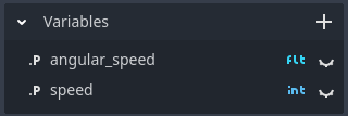
Add movement speed
To define the movement speed variable:
- Click the button to add a new variable in the Variables component section.

- Give the variable the name
speed, and press enter. - Select the variable in the Component view to have the Inspector display the variable's details.
- In the Inspector, change the
Typeto anIntegerand assign a default value of400.
Add angular speed
To define the angular speed variable:
- Click the button to add a new variable in the Variables component section.
- Give the variable the name
angular_speed, and press enter. - Select the variable in the Component view to have the Inspector display the variable's details.
- In the Inspector, change the
Typeto anFloatand assign a default value of3.14.
Angles in Godot work in radians by default, but you have built-in functions available if you prefer to work with degrees.
Apply rotation
To move our icon, we need to update its position and rotation every frame in the game loop.
We can use the Process event, a Godot virtual override function, to do this.
If your orchestration extends a class that extends the Node class, like Sprite2D, this function will be called every frame and provide an argument called delta, which is the elapsed time since the last frame in seconds.
Games work by rendering many images per second, each called a frame, and they perform this in a loop. We measure the rate at which a game produces these images in Frames Per Second (FPS). Most games aim for 60 FPS, although you might find values lower or higher.
We are going to add the Process Event node much like we did the Init Event node.
- Press the button on the top-right of the Functions panel.
- In the All Actions dialog, locate the
Processevent, in the Methods > Node category. - To add the node, either press Add or simply hit Enter.
With the Process event node on the graph, we need to connect logic to this node to perform this computation, but visually:
rotation += angular_speed * delta
The above line increment's the sprite's rotation every frame.
Here rotation is a property inherited from the Node2D class, which Sprite2D extends.
This means that we can work directly with the rotation property in the orchestration.
To do this visually, we need to add several more nodes to our graph:
- Right-click the graph to open the All Actions dialog.
- Search for
Get Rotation. - Select the
Get Rotationchoice and either press Add or simply hit Enter. - Right-click the graph again to open the All Actions dialog.
- Search for
Set Rotation. - Select the
Set Rotationchoice and either press Add or simply hit Enter. - Right-click the graph area once more to open the All Actions dialog.
- Search for
Multiply. - Select the
Float Multiply Floatchoice that is under the Types > Float > Operators category. - Either press Add or simply hit Enter.
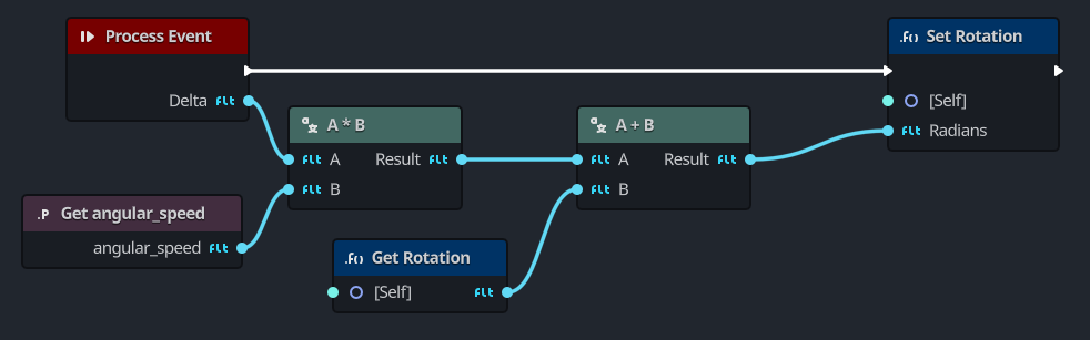
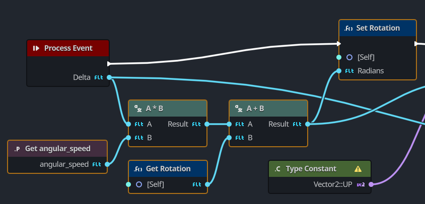
Finally, match all the nodes as shown here.
This visually represents the rotation += angular_speed * delta logic.
Run the scene in the editor to see the icon turn in-place.
Apply movement
Let's now make the node move. In order to do this, we need to add one additional step inside the Process event node logic.
var velocity = Vector2.UP.rotated(rotation) * speed
position += velocity * delta
In this code, we are using a variable named velocity to represent the direction and speed.
To make the node move forward, we start from Vector2.UP, a vector that simply points up, and we rotate it by calling the Vector2 method rotated().
This expression, Vector2.UP.rotated(rotation), is a vector that points forward relative to our icon.
By multiply this by our speed property, it gives us a velocity that we can use to move the node.
And finally we multiply this velocity with the delta time, and add that the node's current position for it to move per frame.
To set this up visually, we need to:
- Right-click the graph to open the All Actions dialog.
- Search for
Type Constant - Select the Type Constant node and set the type as
Vector2and the constant asUPin the Inspector. - Right-click the graph to open the All Actions dialog.
- Search for
Rotated, selection the choice under the Vector2 category. - Next add three math operator nodes
- Multiply
Vector2byInteger. - Multiply
Vector2byFloat. - Addition
Vector2byVector2.
- Multiply
- Finally add two function call nodes
- Search for
Get Position - Search for
Set Position
- Search for
With the nodes, we connect them as shown here:
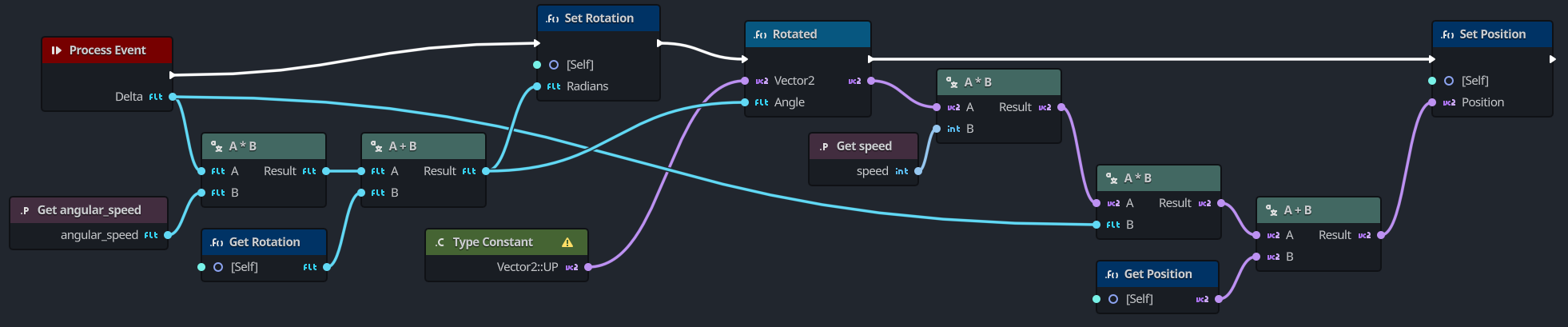
Run the scene to see the Godot head run in circles.
Moving nodes like this does not take into account collisions with other objects. In a future tutorial, you will learn another approach to moving and detecing collisions.
Complete script
Here is what the complete sprite_2d.torch orchestration script looks like for reference.
Refactor and use functions
A common task in programming is to polish code so that it's easier to digest and understand. One of the common complaints of visual scripting is that it's a massive web of connections, and what we've done already is shaping up to be just that. Thankfully, Orchestrator provides multiple tools to help with this, and the first is to use user-defined functions.
Moving apply rotation to a function
The first task we're going to focus on is moving the Apply Rotation logic to a user-defined function called apply_rotation.
This user-defined function will accept the delta time in seconds.
To create the user-defined function:
- Press the button on the top-right of the Functions panel in the Component view.
- When prompted for a function name, enter
apply_rotationand press Enter. - In the Inspector view, click the Add Inputs button to add a new argument to the function.
- Set the name of the argument from NewParam to
delta. - Set the argument's type by clicking the Any button and selecting
Float.
The Function Entry node should now look like this in the graph:
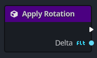
You will have noticed that a new tab has been created at the top of the graph workspace called apply_rotation.
One of the benefits with Orchestrator is that all user-defined functions are organized in their own graph.
This helps to declutter large graphs, and serves as a really neat way to organize your code.
Now, you may wonder how do we get the nodes we created in the EventGraph into this user-defined graph.
Orchestrator supports bulk operations, so we're going to use ![]()
![]()
Left-click anywhere on the graph canvas and select the nodes that are specific to the rotation logic. The following shows the nodes you should be selecting in case you may have forgotten, they're highlighted with a yellow border:
You can also hold the Ctrl key and left click each node separately to select multiple nodes.
Now to move these nodes to the user-defined function, we're going to first Copy them rather than use Cut:
- Press the
Ctrl+Cshortcut to copy the selected nodes into the selection buffer. - In the Component view, double-click the
apply_rotationfunction or click theapply_rotationtab. - In the
apply_rotationgraph, pressCtrl+Vto paste the selected nodes onto the graph.
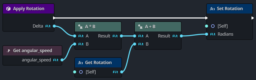
The next step here is to wire up the Function Entry node and the nodes that you just added.
- Connect the
deltaoutput pin to theAinput pin of the multiplication node. - Connect the output execution pin from the Function Entry node to the input execution pin of the Set Rotation node.
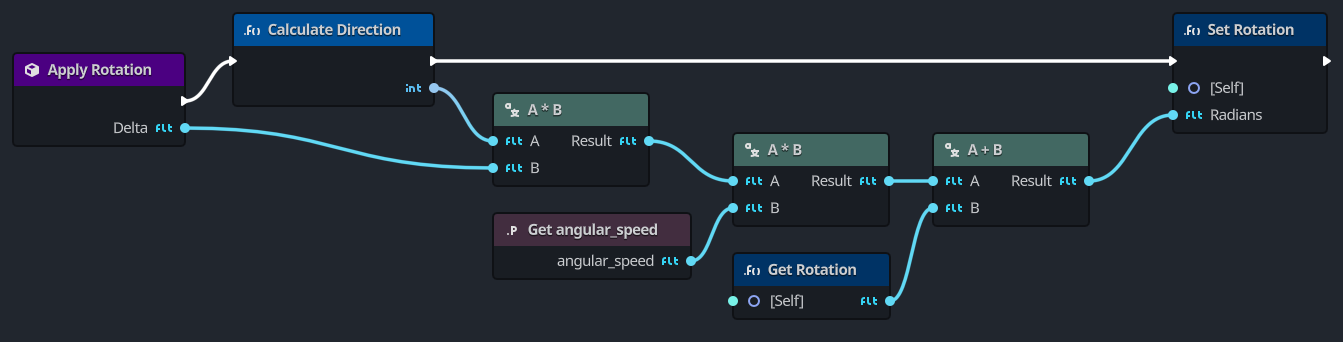
The user-defined function, apply_rotation, should look like this:
The last step is to replace the logic in the EventGraph with our new function, apply_rotation.
Click on the EventGraph in the Graphs section of the Component view or select the EventGraph tab.
- Right-click one of the currently selected nodes.
примечание
If the nodes are not still selected, please reselect them using the procedure above.
- With the nodes selected, right-click one of the selected nodes and select
Deletefrom the context-menu. - Drag the
apply_functionfrom the Component view onto the graph. SelectAdd Call Functionfrom the context-menu. - Connect the output execution pin from Process Event node to the input execution pin of Call Apply Rotation node.
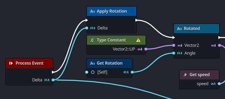
- Connect the output
deltapin from the Process Event node to the inputdeltapin of Call Apply Rotation node. - Connect the output execution pin from Apply Rotation to the Rotated node.
- Open the All Actions dialog, search for
Get Rotationand add it to the graph. - Lastly connect the output in from Get Rotation node to the
anglepin of the Rotated node.
Your EventGraph should now look like this:
Moving apply movement to a function
Now that we have moved the logic for rotation to a user-defined function, the next step is to do the same for Apply Movement.
- Press the button on the top-right of the Functions panel in the Component view.
- When prompted for a function name, enter
apply_movementand press Enter. - In the Inspector view, click the Add Inputs button to add a new argument to the function.
- Set the name of the argument from NewParam to
delta. - Set the argument's type by clicking the Any button and selecting
Float.
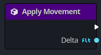
The Function Entry node should look like this in the graph:
Now again, we're going to select and Copy the nodes from the EventGraph into our new apply_movement user-defined function.
- Navigate back to the EventGraph.
- Select ALL nodes except the Process Event and Apply Rotation nodes.
- Press
Ctrl+Cto copy the nodes into the buffer. - Navigate back to the Apply Movement graph.
- Press
Ctrl+Vto paste the nodes onto the graph.
With the nodes pasted, you need to wire up the Function Entry node with the other nodes.
- Connect the output execution pin from the Function Entry node to the input execution pin of the Rotated node.
- Connect the
deltaoutput pin from the Function Entry node to theBinput pin that isn't connected.
This will be theBinput pin on the Multiplication node between aVector2and aFloat.
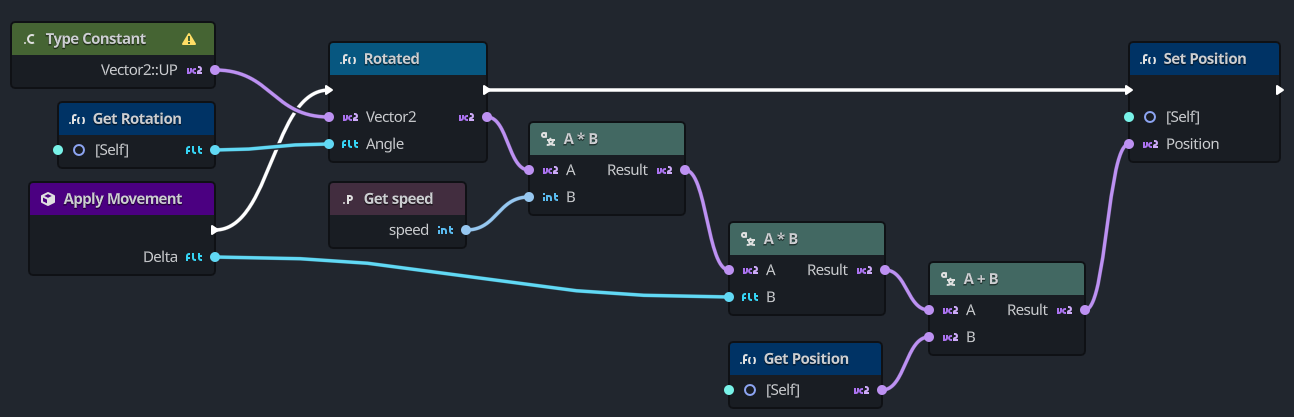
The user-defined function graph should look like this:
The last step is to replace the selected nodes in the EventGraph with the call to the new user-defined function that handles applying movement, apply_movement.
- Delete all nodes in the EventGraph except the Process Event and Apply Rotation nodes.
- Drag the
apply_movementfunction from the Component view onto the graph. Select Add Call Function from the context-menu. - Connect the Apply Function output execution pin to the Apply Movement input execution pin.
- Connect the Process Event
deltaoutput pin to the Apply Movementdeltainput pin.
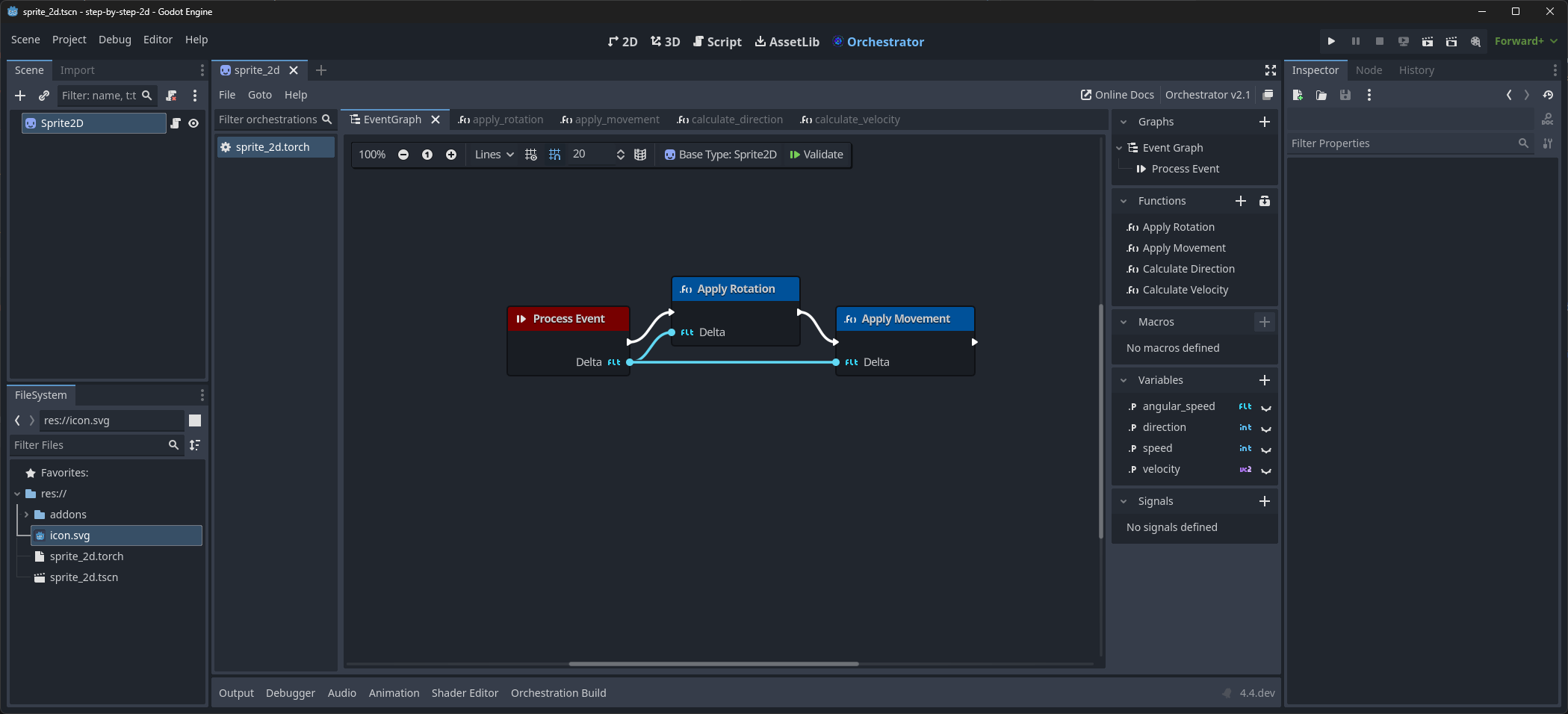
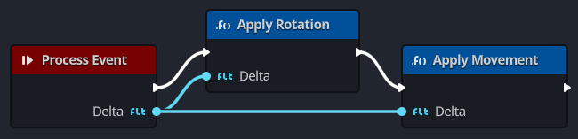
The new refactored EventGraph should now look like this:
By refactoring the logic from the EventGraph into two distinct Function graphs, this makes the graphs more readable.
Any user-defined function can be focused by double-clicking the Call Function node.
For example, double-clicking the Apply Rotation node will open the apply_rotation function graph, and focus the function's Function Entry node.
Listening for player input
Building upon the steps from Creating your first orchestration and Refactor and use functions, let's look at another important feature of any game: giving control to the player.
To add this, we need to modify our sprite_2d.torch orchestration.

You have two main tools to process player input in Godot using Orchestrator:
- Using the built-in event callbacks, mainly Unhandled Input Event.
Like Process Event, it's a built-in function call that Godot will call every time the player presses a key.
It's the tool you want to use to react to events that don't happen each frame, like pressing
Spaceto jump. - Using the Engine Singleton node to access the
Inputsingleton. A singleton is a globally accessible object. Godot provides access to several of these, and they're available in Orchestrator. It's generally the right tool for checking for input every frame.
We are going to use the Input singleton here as we need to know if the player wants to turn or move each frame.
Turning
For turning, we should use a new variable: direction.
In the Component panel, we're also going to create a new user-defined function to calculate the direction.
Calculating the direction
To add the new function, follow these steps:
- Press the on the Functions panel in the Component view.
- Set the new function name as
calculate_direction.
In this function, what we ultimately want to accomplish is this logic:
func calculate_direction():
  var direction = 0
  if Input.is_action_pressed("ui_left"):
    direction = -1
  if Input.is_action_pressed("ui_right"):
    direction = 1
  return direction
Since this function will return an Integer value, we need to add a Function Result node to the graph.
- Click on the Function Entry node if it isn't already selected.
- In the Inspector view, click Add Outputs.
- Click on the button with
Anyand search forInteger, setting the type to integer.
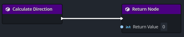
The calculate_direction graph should look like this:
Our direction variable is a multiplier representing the direction in which the player wants to turn.
A value of 0 means the player isn't pressing the left nor the right arrow key.
A value of 1 means the player wants to turn right, while a value of -1 means they want to turn left.
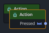
In Orchestrator, to check whether an action is pressed, we need to use the Input Action node. This node allows you to check whether a specific action mapping is pressed, released, just pressed, or just released.
- Right-click on the graph to open the All Actions dialog.
- Search for
Input Action. - Select the
Input Actionchoice and press the Add button or simply press Enter.
We need two of these nodes, one to check ui_left and another to check ui_right.
We can duplicate an existing node by using the Ctrl+D shortcut.
To duplicate the Input Action node:
- Select the Input Action node, if it isn't already selected.
- Press the
Ctrl+Dshortcut or right-click and select theDuplicate option.
You should now have two Input Action nodes, as shown here:
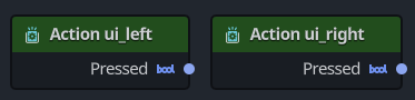
With these two nodes, you need to configure each of them to check for the desired state:
- Select one Input Action node.
- In the Inspector panel, set the
Actiontoui_left. - Select the other Input Action node.
- In the Inspector panel, se the
Actiontoui_right.
These two nodes should now look like this:
Next, to apply the two if conditions, we need use two Branch nodes.
- Right-click the graph to open the All Actions dialog.
- Search for
Branch. - Select the
Branchoption and press Add or simply hit Enter. - Select the Branch Node and duplicate it, so that you have two Branch nodes.
The next thing we need before we can wire up these nodes is a variable to represent the direction value.
In this case, define a variable named direction using the type Integer like had previously defined for speed.
For direction, leave its default value unchanged, as it will default to 0.
If you need a reminder of how to do that, see the Add angular speed section.
With the direction variable setup, drag the direction variable from the Component panel onto the graph 3 times.
Each time, making sure to select that you want to create a Set direction node.
Now one of the cleanest ways to represent a sequence of operations, like checking two if (Branch) conditions followed by some logic that will run based on the prior stages is to use a Sequence node.
In our case, we're going to create a Sequence node that will have 4 output execution pins, one to initialize our direction variable, two to handle the two if checks, and lastly one to handle the incrementing of the rotation.
- Right-click the graph and open the All Actions dialog.
- Search for
Sequence. - Select the
Sequenceoption and press Add or simply press Enter. - In the Sequence node, press the button so that there are 4 output execution pins.

These pins will be labeledThen 0,Then 1,Then 2, andThen 3. - Connect the
Then 0output execution pin to one of the Set direction nodes. - In that Set direction node, make sure that the
directionvalue is0(the default).
Now, lets wire up the nodes.
- Starting with the Sequence node, connect the
Then 1output pin to one of the Branch nodes. - Connect the Action ui_left node's output pin to the
Conditioninput pin of that Branch node. - Connect the Branch node's
Trueoutput execution pin to one of the Set direction nodes. - Set the
directioninput value to-1on the Set direction node.
At this point, we've taken care of setting up the first if condition for Input.is_action_pressed("ui_left").
Now, we need to repeat this process for the other if condition.
- Starting with the Sequence node, connect the
Then 2output pin to the Branch node that isn't connected. - Connect the Action ui_right node's output pin to the
Conditioninput pin of that Branch node. - Connect the Branch node's
Trueoutput execution pin to the Set direction node that isn't connected. - Set the
directioninput value to1on the Set direction node.
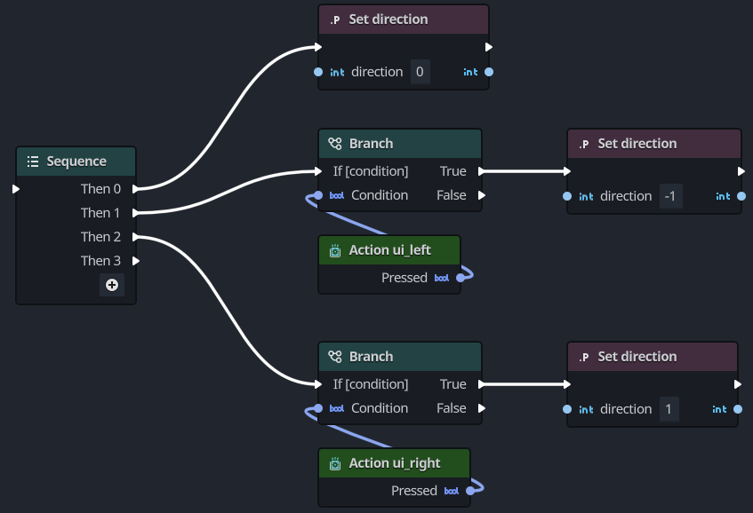
With this, the sequence part of the graph should look similar to this:
Now, you need to wire the Function Entry and Function Result nodes with this, returning the direction.
- Connect the Function Entry output execution pin to the input execution pin of the Sequence node. This will break the existing connection between the Function Entry and Function Return nodes, and that's expected.
- Drag the
directionvariable from the Component view, and spawn a Get direction node. - Connect the
Then 3output pin from the Sequence node to the input execution pin of the Function Result node. - Finally, connect the Get direction node's data output to the input
Return Valuepin of the Function Result node.
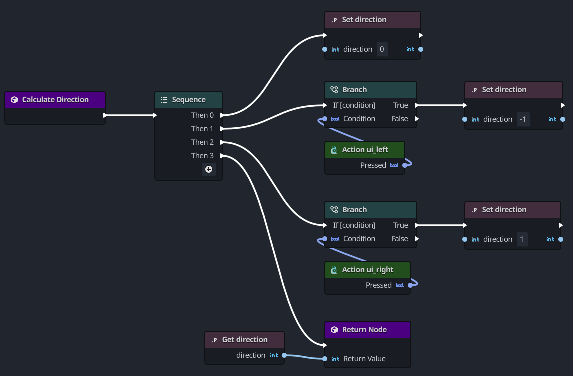
The graph for calculate_direction should look like this:
Using the direction calculation
The last step is to use the calculate_direction function inside our apply_rotation function.
- Navigate to the
apply_rotationfunction, double-clicking it in the Component view. - Drag the
calculate_directionfunction onto the graph from the Component view.
Be sure to select the Add Call Function option from the context-menu. - Select the Multiplication node that multiplies two
Floatvalues and pressCtrl+Dto duplicate. - Connect the Apply Rotation entry node output execution pin to the input execution pin of the Calculate Direction node.
- Connect the
deltaoutput pin on Apply Rotation to theBinput of the duplicated Multiply node from step 3. - Connect the
Return valueoutput pin on the Calculate Direction to theAinput of the duplicated node. - Connect the duplicated node's output pin to the unconnected Multiplication node
Apin. - Lastly connect the Calculate Direction output execution pin to the Set Rotation input execution pin.
The final graph should look like this:
If you run the scene, the icon should rotate when pressing the Left and Right arrow keys.
If you don't press either of the arrow keys, it will simply move forward, and off the screen.
So be sure to constantly press the Left or Right arrows to keep in on the screen.
Moving forward
Now, as nice as this simple game is at this point, we'd like to have better control of our Godot icon.
In this section, we're going to adjust how apply_movement works, and only have the icon move when the player presses the Up arrow key.
This will make the icon easier to control and keep on on the screen.
Calculating the velocity
If you recall when we originally designed the apply_movement function, we used the following to calculate the velocity.
var velocity = Vector2.UP.rotated(rotation) * speed
Now instead, we want to conditionalize this, having the velocity set to Vector2.ZERO, and only applying the calculation if the player has pressed the Up arrow key.
var velocity = Vector2.ZERO
if Input.is_action_pressed("ui_up"):
  velocity = Vector2.UP.rotated(rotation) * speed
We're going to accomplish this by introducing a new function called calculate_velocity.
- Press the button at the top of the Functions panel in the Component view.
- When asked for a function name, enter
calculate_velocity.
In this function, we either want to return Vector2.ZERO if the player has not pressed the Up arrow key, or return the velocity based on the current rotation and speed values.
The first step we need to is to add the Function Return node, returning a Vector2 value.
- Select the Function Entry node.
- In the Inspector view, click the Add Outputs button to add the return node.
- In the Inspector view, set the return value's type to
Vector2fromAny.
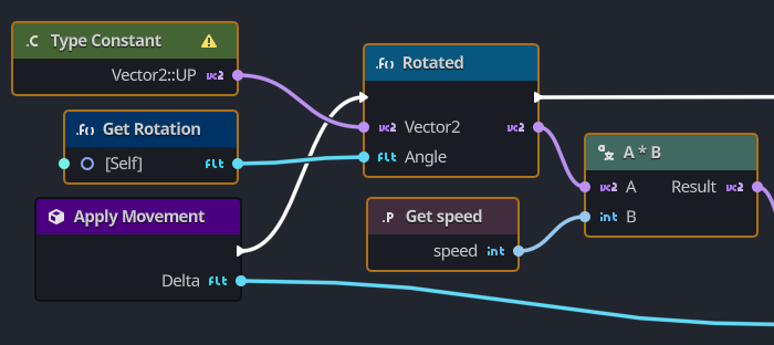
Now to simplify things, navigate back to the apply_movement graph and select these nodes.
The nodes to select are highlighted with a yellow border:
- Press the
Ctrl+Cshortcut to copy the nodes into the copy buffer. - Navigate back to the
calculate_velocityfunction. - Press the
Ctrl+Vshortcut to paste the nodes onto the graph.
With these nodes in the calculate_velocity function, you are going to use a similar technique that was used for direction, relying on a Sequence node to:
- Initialize the
velocityvalue toVector2.ZERO - Check whether the
ui_upaction is pressed, and only modifying thevelocityiftrue. - Return the calculated
velocityvalue.
Before we add nodes, you need to create a velocity variable.
This variable should be of type Vector2, and its default value left unchanged.
If you don't remember the steps, you can refer to the Add angular speed section once more.
With the velocity variable added, perform these steps:
- Right-click the graph to open the All Actions dialog.
- Search for
Sequence. - Select the
Sequenceoption and press the Add button or simply hit Enter. - Connect the output execution pin from the Calculate Velocity node to the input execution pin of the Sequence node.
- Drag the
velocityvariable from the Component panel onto the graph. - Connect the
Then 0output pin on the Sequence node to the input execution pin on the Set Velocity node. - Open the All Actions dialog, and add a Branch node to the graph.
- Connect the
Then 1output execution pin to the input execution pin of the Branch node. - Open the All Actions dialog, and add an Input Action node to the graph.
- Select the Input Action node.
- In the Inspector view, change the
Actionproperty to beui_up. - Connect the Input Action output pin with the input
Conditionpin on the Branch node. - Connect the
Trueoutput pin from the Branch node to the input execution pin on the Rotated node. - Select the
velocityvariable in the Component panel and drag onto the graph, selecting Set velocity. - Connect the output execution pin from Rotated to the input execution pin of **Set Velocity.
- Connect the output pin from the Multiplication (A*B) node to the input pin of Set Velocity.
- Drag the
velocityvariable from the Component panel and select Get velocity. - Connect the
Then 2output execution pin to the Return Node input execution pin. - Finally, connect the Get velocity output pin to the Return Node input
Return Valuepin.
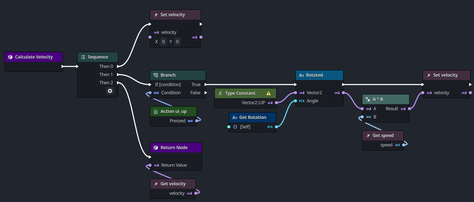
At the end, your graph for calculate_velocity should look like this:
Using the velocity calculation
With the calculate_velocity function done, we need to use this in the apply_movement function.
Navigate back to the apply_movement function and perform these steps:
- Remove the node that you copied to the
calculate_velocityfunction.
In case you forgot, they're the ones shown here with a yellow border: - Drag the
caculate_velocityfunction from the Component view onto the graph.
Again, select the Add Call Function option from the context-menu. - Connect the output execution pin from Apply Movement to the input pin on Calculate Velocity node.
- Connect the output execution pin from Calculate Velocity to the input execution pin on Set Position node.
- Finally, connect the
Vector2output pin on Calculate Velocity node to the inputApin on the Multiplication node that's currently unconnected.
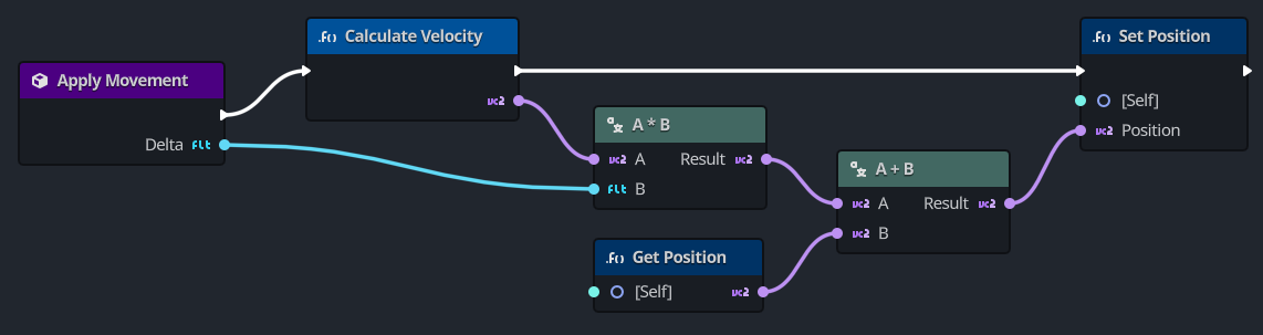
The new simplified apply_movement function should look like this:
If you now run the scene, you'll notice the following happens:
- The Godot icon does not move unless you press the
Left,Right, orUparrow keys. - The
Leftarrow key rotates the icon to the left. - The
Rightarrow key rotates the icon to the right. - The
Uparrow key makes the icon move forward in its current facing direction.
Summary
In summary, every script in Godot represents a class that extends one of the engine's built-in classes.
The node types your classes inherit from give you access to properties, such as rotation and position in our sprite's case.
You also inherit many functions, which we didn't use in this example.
In an Orchestration, using variables is an excellent way to store and manage state. Additionally, user-defined functions are a great way to organize smaller pieces of code to reduce the complexity of large visual script graphs.
And who would have thought, visual scripting can be done without being spaghetti!